How to Make a Simple IoT Car
Introduction
Gear up for an exciting venture into the world of remote-controlled RC cars! In this tutorial, we’ll guide you through the process of crafting your very own RC car that you can command over the internet using the Blynk app on your smartphone.
Prerequisites:
Tools
- Computer (Windows/Mac/Linux) with internet connection & web browser (Chrome/Firefox/Edge)
- Wi-Fi or Hotspot & its credentials (Wi-Fi name & password)
- NodeMCU Development Board (ESP8266) & compatible USB cable.
- An Email account to create Blynk account.
Components
| Name | Specification | Quantity |
|---|---|---|
| NodeMCU board | - | 1 |
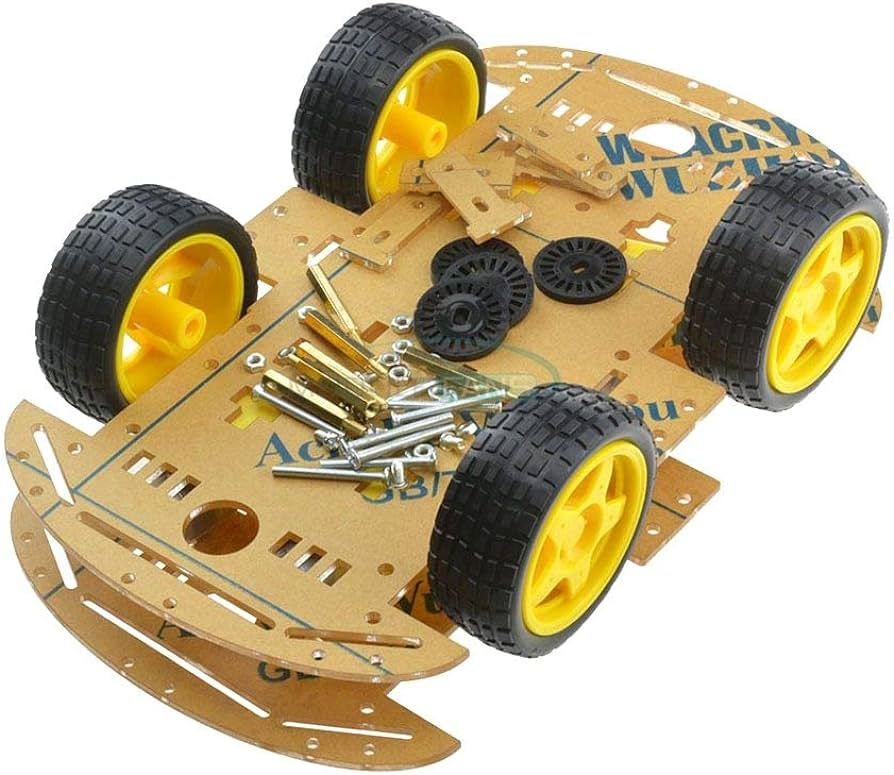
| RC Car kit | 4 Wheel | 1 |
| Motor driver | L298N | 1 |
| Rocker switch | - | 1 |
| Lithium-ion battery | 18650 3.7V | 2 |
| Dual 18650 battery holder | - | 1 |
| Dual 18650 battery charger | - | 1 |
| Jumper wires | F to F | 10 |
| Jumper wires | M to M | 5 |
| Multi-stand wires | - | 1 Meter |
| Double tape | - | 1 |
| Screw driver | M3 (3mm) Star | 1 |
| Wire stripper - cutter (optional) | - | 1 |
Arduino IDE:
Download Arduino IDE software:
- Visit the official Arduino website at www.arduino.cc/en/software
- Click on the “Windows Installer” link to download the latest version of the Arduino IDE for Windows. This will typically be a
.exefile.
Run the Installer:
- Locate the downloaded installer file and double-click on it to run it.
- Follow the software’s recommended settings and click ‘Next’ for all the prompts.
Driver Installation (if needed):
- During the installation, you may be prompted to install drivers for certain Arduino boards (e.g., Arduino Uno). Follow the on-screen instructions to install the necessary drivers.
Completing the Installation:
- Once the installation is complete, you’ll see a “Completing the Arduino” window. Ensure that the “Launch Arduino” option is checked and click “Finish.”
Additional Driver installation for ESP8266 boards:
- Plug your NodeMCU board into a USB port on your computer using a suitable USB cable and open “Device manager” tool.
- In the Device Manager, expand the “Ports (COM & LPT)” section and look for device entry that has warning icon in it.
- If you don’t see warning icon you can skip this step.
- Visit https://www.silabs.com/developers/usb-to-uart-bridge-vcp-drivers and click on “Downloads” tab.
- Click on “CP210x Universal Windows Driver” link and a download should start.
- Once download is completed locate the downloaded driver package (usually a .zip file) and extract its contents to a folder on your computer (open zip file with File explorer and click on “Extract all” button).
- Using Windows File Explorer, locate the driver folder (that you previously unzipped)
- Right click on the
silabser.inffile and select Install & Follow the instructions. - Once the installation is complete, you should see a message indicating that the driver installation was successful. Click “Finish” to exit the installer.
- To verify that the driver has been installed correctly, open the Windows Device Manager. You should see an entry for “Silicon Labs CP210x USB to UART Bridge” with a COM port number assigned to it (e.g., COM3).
- If you’re using the Arduino IDE to program your NodeMCU board, close and restart the IDE to ensure it recognizes the newly installed driver.
Install Additional Board Packages:
- Go to File > Preferences and in the Additional Boards Manager URLs field, add this URL
https://arduino.esp8266.com/stable/package_esp8266com_index.json - Go to Tools" > Board > Boards Manager and search esp8266 and click install button (make sure you have internet during this step).
- Go to File > Preferences and in the Additional Boards Manager URLs field, add this URL
Install Additional Libraries:
- You can install libraries to extend the functionality of your Arduino projects. Go to “Sketch” > “Include Library” > “Manage Libraries” to browse and install libraries from the Arduino Library Manager.
- For this project download
Name Version Auther Blynk 1.3.0 or above Volodymyr Shymanskyy
Blynk setup
Open A Web browser and on a new tab open blynk.cloud page, and fill the form to create account.
Once form submitted you’ll receive an email containing Verification link and open it on new tab and congratulation you have successfully created Blynk account.
We recommend installing and logging in on your phone as well. The Blynk App is available for both Android and iPhone, providing a seamless experience.
Now login to blynk.cloud in computer and go to Developers Zone > My Templates page and click + New Template button.
Provide Template Name, Select ESP8266 as Hardware, Wi-Fi as Connection type and optionally provide description. Click Done button.
Click Datastreams tab and click New Datastream button, select Virtual Pin option and provide these values.
Id Name Pin Data type Min Max Default Value 1 Speed V0 Integer 0 255 0 2 Direction V1 Integer 0 4 0 After creating above Datastreams, Click Save button.
Click on Devices in sidebar, click + New Device, select From Template, pick your template that you just created and provide device name (eg: iot-car). Click Create button.
Open Blynk app on your phone and click on 👤 icon, click on “My Profile” and Enable “Developer Mode”. Click 🗙 icon to close it.
Click on Device which you just created and follow video which shows how to setup mobile dashboard in Blynk for IoT Car Project.
Programming
- Open Arduino IDE in your computer and go to File > New then File > Save and provide project name (eg: iot-car) and click save.
- Now copy below snippet and paste into your Arduino sketch and save it.
| |
- Now replace starting 3 lines with Blynk credentials, which can be found under “Device Info” tab in Devices page.
- Now update
ssid[]&pass[]variables values with your Wi-Fi credentials and save the file by pressingctrl sor clicking File > Save. - Once you have saved sketch/code connect your NodeMCU microcontroller board to your computer using appropriate Micro USB cable.
- Before uploading your sketch, you need to select the correct items from the Tools > Board and Tools > Port menus.
- Pick NodeMCU as board by going Tools > Board: > ESP8266 Boards > NodeMCU 1.0 (ESP-12E Module).
- Select port by going Tools > Port > (port name). On Windows, it’s probably
COM3orCOM7- to find out, you look for USB serial device in the ports section of the Windows Device Manager. On the Mac, the serial port is probably something like/dev/tty.usbmodem241or/dev/tty.usbserial-1B1. - Now click on “Upload” icon and wait for it to complete.
- Now ensure NodeMCU is connected to Wi-Fi and Blynk dashboard is showing device is “online” in devices page.
- If its not showing online, check your internet connection and double check provided Wi-Fi credentials are correct.
Hardware setup
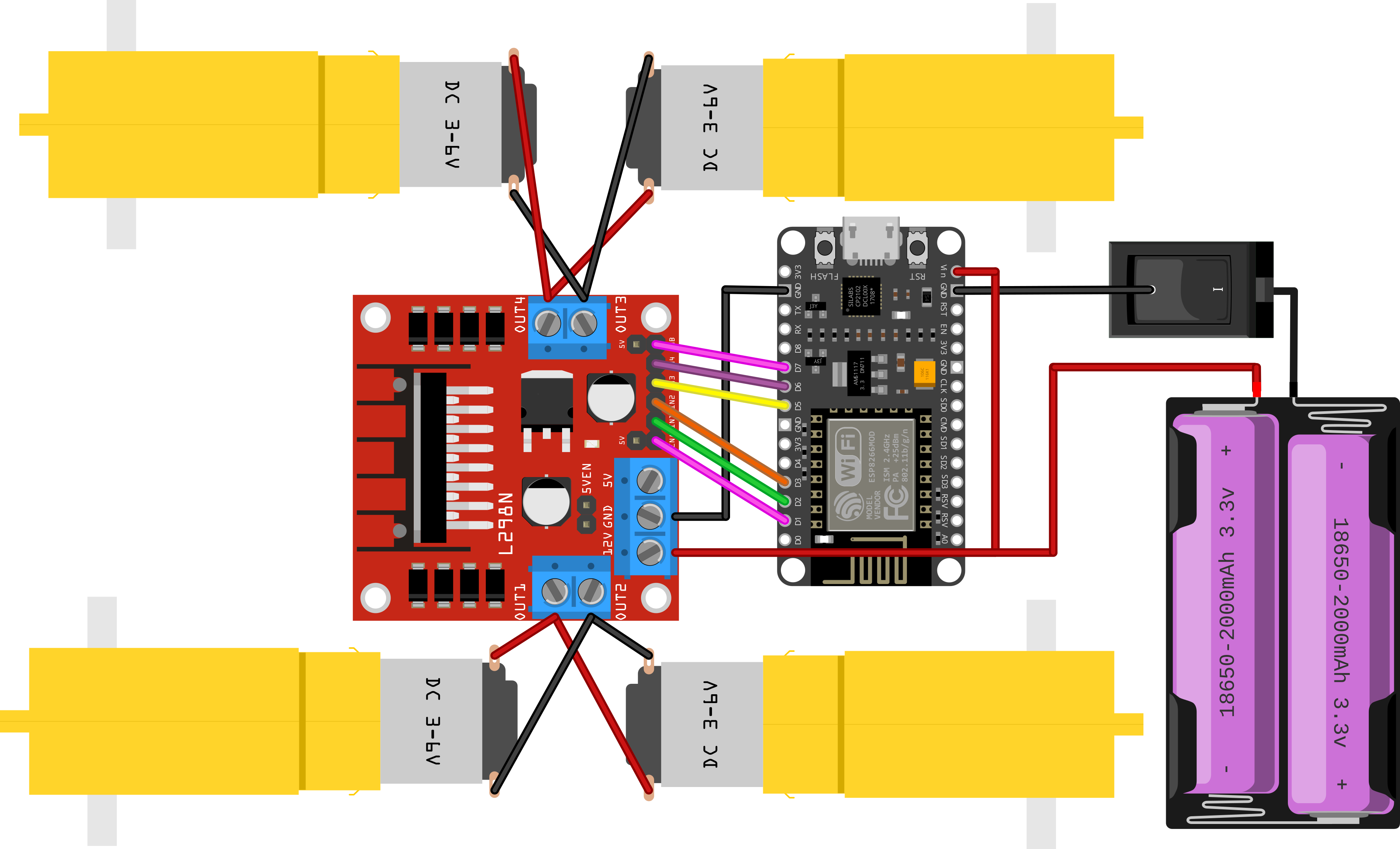
- Disconnect USB cable of your NodeMCU board and start making connection as suggested in above circuit diagram.
- Double check connections then proceed to turn on the switch.
- Make sure NodeMCU is not connected to computer when its being powered through batteries.
- Turn on the switch and check your Blynk app and ensure device is being shown online.
- Set speed to full and start testing all 4 buttons. Ensure motor directions are in proper order.
- Now you can start moving the circuit to chassis, first disconnect all motors from motor driver module and place it on chassis board.
- Start assembling RC car kit as shown in manual (manual is provided in RC car kit box) starting with motors.
- Use double-tape to secure Motor driver, NodeMCU & battery holder on top of chassis.
Congratulations on successfully creating your own Internet-controlled RC car using Blynk and NodeMCU! You’ve not only mastered the art of crafting a customized RC vehicle but also explored the realm of remote control through the power of the internet. As you reflect on your journey, remember that this project is just the beginning. The skills you’ve developed can be expanded to create even more sophisticated projects in the world of electronics and remote control.
Feel free to experiment with additional features, such as adding sensors for obstacle detection or enhancing the app interface on Blynk. The possibilities are limitless, and your newfound knowledge opens doors to a myriad of exciting possibilities in the DIY electronics space.
Thank you for joining us on this adventure. Keep innovating, exploring, and building! Happy making!